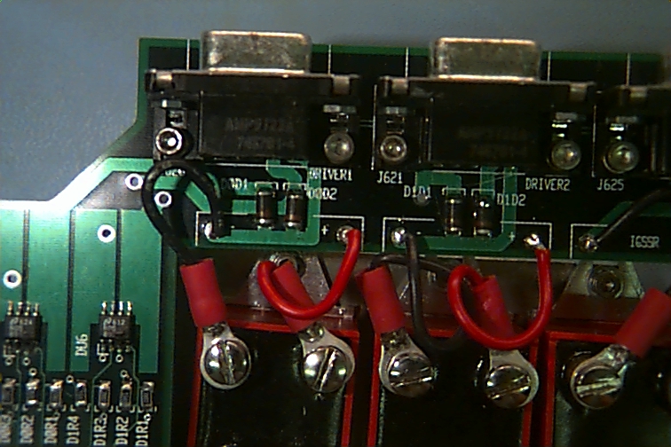
You can see the blown up FETs in this one a little better. Primarily, however, this shot was taken just to document the proper orientation of the diodes, since the silk or silk screen (yep, just like a T-shirt, only much finer) used for the white lettering location marks, was wrong.
You can see negative polarity indicators, which look like like sideways brackets ( ] ), just above the diodes. On the diodes themselves, you can see a red line near the bottom, that indicates the negative side of the diode. So These are in backwards according to the markings, but it's the way they need to be.
Near the FETs, below and to the left, you can see that pin 1 is marked with a little L shaped mark. The FETs themselves have a little indentation, which you can't see here, in the lower left corner, to indicate the position of pin 1.
Just below the FETs are some more diodes. They work the same as the diodes at the top of the picture, but can't handle as much current, so they can be made smaller.
The black and silver things at the top of the picture are connectors, just like you might see on the back of your computer.