Design, Integration and Testing of the TERRIERS Attitude Control and
Determination System
Dr. John Hanson,
Senior Engineer, AeroAstro LLC
Mr. Richard Warner,
Chief Technical Officer, AeroAstro LLC
Mr. Russell Brinkmann,
Senior Engineer, AeroAstro LLC
Abstract
The Tomographic Experiment using Radiative Recombinative Ionospheric EUV and Radio
Sources (TERRIERS) is a satellite scheduled for launch in late 1997 or early 1998.
The goal of the TERRIERS mission is to demonstrate global ionospheric tomography
and to utilize this technique to study ionospheric and thermospheric processes. TERRIERS
is a spin-stabilized satellite with magnetic torque control. Attitude information
is provided by two magnetometers, two body mounted horizon crossing indicators and
a suite of sun sensors. In its science collection mode, it is spinning at 10 RPM in a Thomson
Spinner configuration. AeroAstro LLC has been responsible for the design, manufacturing
and testing of the spacecraft bus, including the complete attitude control system, under contract to Boston University.
In order to test the integrated attitude control system with the spacecraft bus and
payload, a hardware-in-the-loop test is being conducted. In this test, signals to
the attitude control sensors (sun sensors, horizon crossing indicators, magnetometers)
are simulated with hardware. Spacecraft commands to the magnetic torquers are sensed
by an external computer that monitors the spacecraft bus. These commands are used
in a simulation of the spacecraft dynamics. This simulation then controls the ACS
sensor inputs in real time. Using this experimental apparatus, the performance of the
attitude control system is demonstrated and realistic mission simulations are being
performed.
This paper will present details of the design of an attitude control system for a
small satellite. It will also discuss the testing of the attitude control system,
with results from the hardware-in-the-loop test.
Introduction
The Tomographic Experiment using Radiative Recombinative Ionospheric EUV and Radio
Sources (TERRIERS, Figure 1) is a satellite scheduled for launch in late 1997 or
early 1998. The goal of the TERRIERS mission is to demonstrate global ionospheric
tomography and to utilize this technique to study ionospheric and thermospheric processes.
Under contract to Boston University, AeroAstro LLC has been responsible for the
design, manufacturing and testing of the spacecraft bus. This includes the complete
attitude control system (ACS).
The TERRIERS ACS has two general requirements: to move the spacecraft from launch
vehicle tip-off to a spin-stabilized, sun-pointing configuration and to maintain
an acceptable orientation when the payload is taking data. This requires the ACS
to operate in several different modes and to switch autonomously between them (Figure 2).
Within one minute of release from the launch vehicle, the flight computer will have
booted and the ACS will be running. The ACS Mode Switching Logic will move the spacecraft from an arbitrary initial tumble to a spin-stabilized, sun-pointing configuration.
Ground commands will be used to spin the spacecraft up to 10 RPM and to turn the
spacecraft to its data collection configuration.
The science mission requires the primary instruments (Tomographic EUV Spectrographs)
to scan the earth atmosphere at a frequency of 8 to 12 RPM. Rather than use a scanning
platform, when operational, TERRIERS will be spin-stabilized at 10 RPM in a Thomson Spinner configuration, i.e., with the spacecraft spin axis in the same direction
as the orbit normal. TERRIERS is required to maintain this orientation to within
1.5 deg with knowledge to 0.25 deg in the direction of spin and 0.5 deg in any other
direction. Spin rate information is provided to the payload for preprocessing the tomographic
data.

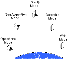
Figure 1: TERRIERS Figure 2: ACS Mode Switching Logic
In order to test the integrated attitude control system with the spacecraft bus and
payload, a hardware-in-the-loop (HITL) test is being conducted. In this test, the
environment seen by the attitude control sensors (sun sensors, horizon crossing indicators, magnetometers) are simulated with hardware. Spacecraft commands to the magnetic
torquers are sensed by an external computer that monitors the spacecraft bus. These
commands are used in a simulation of the spacecraft dynamics. This simulation then
controls the simulated sensor inputs in real time. Using this experimental apparatus,
the functionality of the attitude control system is demonstrated and realistic mission
simulations can be conducted. The goal of these tests is two-fold: to demonstrate
the stability of all of the control systems and to provide confidence during mission
simulations that no interactions between the ACS and the rest of the spacecraft bus
and payload exist.
ACS Hardware
TERRIERS has several different sensors to measure attitude. In the Operational Mode,
the primary ACS sensors are two body-mounted horizon-crossing indicators (HCI's)
that provide roll angle, pitch angle and pitch rate information. One primary and
one backup magnetometer are used to measure the local magnetic field. These signals are
differentiated to provide a measure of spin-rate when the HCI's cannot be used (e.g.,
when the spacecraft is not in the Operational Mode). Seven coarse sun sensors and
four medium sun sensors measure the direction of the sun-line in spacecraft body coordinates.
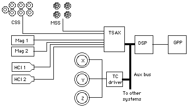
Figure 3: TERRIERS ACS Block Diagram
The TERRIERS ACS block diagram (Figure 3) shows the major hardware components of the
system and how they are connected.
The sun vector is determined by an array of simple photodiodes called Coarse Sun Sensors
(CSS). These sensors utilize the cosine drop off in current from the photodiodes
when the sunlight hits at less than normal incidence and provide low accuracy (5 )
but full sky coverage. There are seven CSS's mounted at various points around the
spacecraft. Four Medium Sun Sensors (MSS) provide a more accurate measure of the
sun vector (0.1 ) over a more limited field of view (~45 from spin axis). These sensors utilize a 4 quadrant photocell illuminated by
an offset aperture. By measuring the current output of each quadrant, the aperture
centroid can be located in the plane of the photocells. The offset of the centroid
from the center of the instrument gives a measure of the sun-line in body axes. The four
MSS's are mounted in a package on the front of the solar array and are pointed along the y-axis. Both sun sensors are manufactured by AeroAstro.
A redundant pair of Schonstedt SAM-73C magnetometers (Mag 1, Mag 2) sense the earth
magnetic field in three axes. These are fluxgate magnetometers and provide 1% field
magnitude accuracy over a 50 mT range and 1 field orientation accuracy. A general concern with magnetometers is
error due to spacecraft generated magnetic fields, either due to permanent magnets
or current loops. While it is common practice to mount these devices on deployable
booms or to place them on the ends of deployable solar arrays to reduce the effects of
such interactions, on TERRIERS both magnetometers are mounted on the backside of
the solar array. The largest potential interaction is with the magnetic field created
by the torque coils. The effect of this interaction is removed in flight by careful calibration
on the ground. The ACS software uses knowledge of the state of the three torque
coils along with an interaction matrix to remove the effect from the raw magnetometer data. Permanent magnetics are reduced by careful material selection and current
loops by careful electrical design.
Two A & M Associates Horizon Crossing Indicators (HCI 1, HCI 2) are used to determine
the earth vector. These are infrared sensors operating in the 15 micron wavelength
to sense the C02 layer about the earth. As the vehicle spins, these instruments will send a pulse
whenever their narrow FOV's cross from the sky-to-earth or from earth-to-sky. These
crossings are called "lead" and "trail" crossings, respectively. The two HCI's are
mounted in the yz-plane such that they point 30 deg offset from the z-axis. This makes
the two instruments scan different paths over the earth as TERRIERS spins.
The actuators used on TERRIERS are an orthogonal set of torque coils that generate
moments by interaction with the earth magnetic field. They have a full-scale range
of 8A-m2 and are controlled by a very high efficiency pulse width modulator that provides
12 bits plus sign resolution. Each of the three axes has redundant coils and drivers.
The driver board has the capability to compensate for coil resistance changes due
to temperature and bus voltage changes due to battery level (both of which affect the
coil scale factor). The coils and coil drivers are manufactured by AeroAstro.
Analog sensor (sun sensor, magnetometer) signals are wired up to a data acquisition
board called the TSAX board. This board contains signal conditioning circuits and
a 16 bit A/D converter. The HCI pulse signals are routed through the TSAX board
to the main processor, where they generate an interrupt to allow for very accurate timing.
This interrupt is handled in real time by the system software. When an interrupt
is received, the system software stores the current spacecraft clock reading in a
buffer and increments a counter. When the counter reaches four, the HCI's have registered
one lead and one trail crossing each and the ACS can use the information on its next
software cycle to compute the spacecraft attitude. After processing the HCI data,
the ACS resets the counter to zero and the process repeats.
The TSAX board and the coil driver board communicate with the processing system via
a redundant, error detecting, serial bus called AUX. Virtually all spacecraft subsystems
are controlled by the AUX bus. Some of the advantages of this digital bus approach are ease of expansion and the ability to develop subsystems without needing a spacecraft processor to generate AUX commands (since AUX cycles can be generated
by any desktop computer). In addition, during ground testing, the spacecraft AUX
bus can be taken over by ground support equipment to allow direct control and interrogation of subsystems. The AUX bus can also be monitored by external hardware without
interfering with its operation. This capability is used in the HITL test as described
below. The TSAX and processor are manufactured by AeroAstro.
ACS Software
The TERRIERS attitude control system software runs at 4 Hz. Each execution of the
software can be divided into several steps:
- Read all ACS sensors (magnetometers, sun-sensors, horizon crossing
indicators).
- Process and filter raw sensor data to get usable information.
- Based on the processed sensor data, switch into the appropriate control
mode.
- Compute control torques for the control mode.
- Issue current commands to magnetic torque coils.
- Send appropriate information to the payload.
All of the ACS sensors are sampled through the TSAX board as previously described.
The raw data from the sensors are used to generate a usable, filtered reconstruction
of the vehicle state.
The magnetometer data is transformed from a voltage measurement into a magnetic field
measurement in spacecraft body axes. This is filtered prior to use by the ACS.
Additionally, the signal is differentiated to get a measure of the spacecraft spin
rate. However, only that portion of the spin vector that is perpendicular to the magnetic
field line is observable from magnetic field measurements.
The current measurements from the CSS and MSS package are used to generate an estimate
of the sun vector in body axes and to indicate when the spacecraft is passing into
or out of eclipse. The former is filtered prior to use by the ACS, while the latter
is sent to the payload for use in governing the operation of instruments.
When four HCI interrupts have occurred, the ACS will compute a new estimate of the
vehicle attitude. Figure 4 shows a typical scanning path of the two HCI's and the
timing diagram for the related interrupts. By averaging the four crossing times,
a measure of the time of zenith crossing is derived. By taking the difference in this time
between two sequential sets of data, the spin rate is derived. The roll angle of
the vehicle is related to the difference in the lengths of the paths swept out by
the two HCI's. That is, the roll angle is a function of the difference between the times
taken by each HCI to record a lead interrupt and then a trail interrupt. The time
of zenith crossing is passed to the payload for preprocessing of the tomographic
data.

Figure 4: HCI Operation
Based on the processed sensor data, TERRIERS will autonomously select the appropriate
control mode. Transition from one mode to the next is defined by parameters stored
in EEPROM. These parameters can be modified in flight to change the characteristics
of the mode switching logic.
A typical sequence of this logic follows:
Wait Mode
(0) - Within one minute of release from the launch vehicle, the flight computer
will have booted and the ACS software will be running. For the first three minutes
of the mission, the ACS will be in the Wait Mode where the magnetometers and sun
sensors are sampled at 4 Hz and 1 Hz, respectively, but no control torques are applied. This
will allow filters on the sensor signals to become initialized and prevent large
initial control torques.
Detumble Mode
(1) - Once the Wait Mode is completed, the ACS will switch into the Detumble Mode.
The rate of change of the magnetometer signal is fed back to the torque coils with
the goal of reducing the spin rate of the spacecraft in all axes. While only that
portion of the spin rate that is normal to the magnetic field lines is observable, that
is also the only portion of the spin rate that is controllable with magnetic torque
coils.
Spin-up Mode
(2) - When the total angular velocity of the satellite has been reduced, the ACS
will shift into Spin-Up Mode. The magnetometer is used to estimate the angular velocity
of the vehicle, and the x and z torque coils are actuated alternately to spin the
spacecraft up around its y-axis. This controller uses proportional feedback, but the
gains are selected to be very large, making it a bang-bang system. The nutation
of the spin axis is damped by use of a "minus-K-Bdot" controller (Wertz, p. 630).
Sun-Acquisition Mode
(3) - When the spin rate has increased to 1 RPM, the ACS switches into Sun Acquisition
Mode and turns the solar panel (+y axis) to point at the sun. Obviously, as the
spacecraft passes into eclipse, the ACS will switch out of this mode and back into
the Spin-Up Mode, but as soon as the vehicle passes out of eclipse, it will switch back
into Sun Acquisition Mode. This controller is a Digital Linear Quadratic Regulator
(DLQR) and regulates the spin rate as well as the sun-pointing angles. After TERRIERS
has acquired the sun and reduced the angle between the solar panel and the sun-line
to zero, it will remain in the Sun Acquisition Mode. This configuration, with the
solar panel normal to the sun-line, provides the maximum power to the spacecraft,
has a benign thermal environment and will allow all subsystems to be tested prior to moving
to the Operational Mode. The ACS Mode Switching Logic will not switch the spacecraft
into the Operational Mode. This can only be done by issuing a command from the ground station.
Ground Command Mode
(4) - Before it can be placed in a Thomson Spinner configuration, the spin axis
must be moved from pointing at the sun to pointing along the orbit normal and the
spin rate must be increased from 1 RPM to 10 RPM. Since it is in a 9 am to 9 pm
sun-synchronous orbit, the spin axis must be turned by a total of 45 degrees. This is done by
issuing time-tagged body torque commands from the ground. While in the Ground Command
Mode, the ACS will issue no torque commands. This will keep it from stepping on
commands issued by the ground, and is also useful as an emergency mode in case of ACS malfunction. This mode can be entered only by direct command from the ground. The ACS Mode
Switching Logic cannot switch into this mode autonomously.
Operational Mode
(5) - Once the vehicle spin axis has been turned by about 20 degrees and the spin
rate has been increased to 10 RPM (again by time-tagged body torque commands), the
ACS will be switched into the Operational Mode (Figure 5) and the spacecraft will
reduce its roll and yaw angles autonomously. In this mode the spacecraft attitude is defined
relative to local vertical coordinates by a body 3-1-2 rotation. These rotations
are called yaw, roll and pitch, respectively. The basis vectors for the local vertical system are nx in the direction of spacecraft velocity, ny in the direction of the orbit normal and nz in the anti-nadir direction. For small yaw and roll angles, roll is a rotation about
nx, yaw is a rotation about nz, and pitch is a rotation about ny. The spin-rate, then, is the rate of change of the pitch angle. The horizon crossing indicators measure roll angle, spin rate and the time at which
nadir crossing occurs. Since roll and yaw are coupled by the motion of the vehicle
in the orbit, controlling roll is sufficient to control both roll and yaw. The roll
controller was designed with frequency techniques in the digital domain. This controller
has one zero and two poles, which puts the crossover of the closed loop system at
approximately 0.0004 Hz and provides positive damping to the system. The torque
commands are computed in local vertical coordinates every time an updated attitude is computed
by the HCI's. These are transformed into body axes using the estimate of the spacecraft
spin rate. The modes associated with the nutation of the spin axis are controlled at 4 Hz with a "minus-K-Bdot" controller. The spin rate control requires only
proportional feedback.
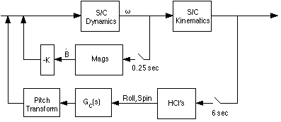
Figure 5: Operational Controller
Hardware-in-the-Loop Test
The most exhaustive test of the TERRIERS attitude control system is the hardware-in-the-loop
(HITL) test. In this test, the spacecraft is run under conditions as near to actual
operating conditions as is feasible. The TERRIERS HITL setup is shown in Figure 6. The central piece of HITL equipment is the simulation computer (Macintosh Quadra
950, with a 33 MHz Motorola 68040 CPU). The simulation computer uses the commanded
current to the torque coils to integrate the spacecraft dynamic forward in time.
This simulation includes a full non-linear dynamic model of the vehicle, orbit mechanics
and potential errors such as misalignments of the actuators and sensors relative
to body axes. The simulation is run in a poling loop with the TERRIERS ACS, running
on the spacecraft, controlling the rate of the loop. It would have been better to use an independent artificial environment simulator,
but budget constraints necessitated the use of the same simulator used to develop
control algorithms.
A piece of ground support equipment, called a "snooper," watches the data traveling
over the AUX bus, in effect, eavesdropping on spacecraft AUX commands. Commands to each of the three torque coils occur only once per ACS cycle. The
snooper presents one CRC (error detection code), one command byte and 16 data bits to the simulation computer for each torque command.
The simulation computer sorts this data and integrates the spacecraft equations
of motion forward in time for 0.25 seconds. At the end of this integration step,
the simulation computer issues commands to stimulators attached to the TERRIERS ACS sensors.
These stimulators trick the spacecraft into thinking that it is actually on orbit
with appropriate magnetic field, solar and earth stimuli. The simulation computer
then waits for the snooper to read the next set of torque commands (indicating that
the ACS has completed another 0.25 second cycle) before continuing its integration.
For each of the primary sensors, physical stimulation, controlled by the simulation
computer, is provided. For the MSS, a secondary or backup ACS system, the sensors are bypassed and the sensor AD board (TSAX) is stimulated directly. Communication
between the MSS and magnetometer stimulators and the simulation computer is done
over a common AUX bus (isolated from the spacecraft AUX bus). However, for the HCI and CSS, a parallel
bus is used with each bit corresponding to a specific action.
Initially, an attempt was made to stimulate each MSS with a collection of LED's, each
controlled by a PWM circuit. Unfortunately, these LED's generate insufficient light
to properly stimulate the sensor. Instead, the MSS package is bypassed entirely
and each MSS input to the TSAX is stimulated directly by a PWM signal run through a low-pass
filter. This system has a rise time of 0.333 sec from 0 to 5 V and a ripple voltage
of roughly 8% of full-scale at the PWM frequency of 1.9 kHz. The ripple voltage
is filtered by the TSAX anti-aliasing filters, resulting in a millivolt level oscillation
in the raw MSS signal, as seen by the ACS.

Figure 6: TERRIERS Hardware-in-the-Loop Setup
Each CSS is stimulated by a single infrared LED. Two bits from the simulation computer
control two bias currents through the LED and, consequently, the apparent intensity
of the sun seen by each CSS (Figure 7). Since there are only two bias levels to adjust, it is fairly easy to compensate for the nonlinearities of each LED's brightness-current
curve.
The active magnetometer is placed in a Helmholtz cage that has three orthogonal electromagnetic
coils, each driven by a pulse-width modulated circuit (Figure 8). Note that the Helmholtz driver is just a prototype torquecoil driver, thus reducing
design effort. By carefully aligning the magnetometer and cage axes and using dual coils to minimize
near field effects, off-axis coupling between the coils and the magnetometers is
kept below 10%. Furthermore, the interaction between the stimulation coils and the
magnetometer is fully calibrated. Initial tests of this device in the Boston University
cleanroom showed large fluctuations of the ambient magnetic field with particularly
large oscillations (~1% of steady state) at 60 Hz. In order to reduce this noise
to acceptable levels, a mu-metal shield is placed around the cage. The resulting performance
of the system is shown in Figure 9. Here, a comparison of expected and measured
magnetic field is made when the spacecraft is spinning at 10 RPM and indicates that
the Helmholtz cage is quite effective.
As mentioned previously, the HCI's sense the 15 micron emission line of CO2 in the Earth atmosphere. In the HITL test, an HCI is stimulated by opening and closing
a shutter between it and a heat source, in this case a halogen lamp (Figure 10).
Timing signals are provided by the simulation computer to small stepper motors that
move the shutters open and closed in 60 to 70 msec.


Figure 7: CSS Stimulator Figure 8: Magnetometer Stimulator
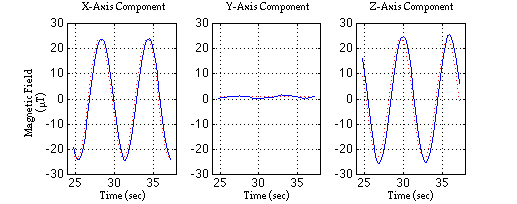
Figure 9: Magnetometer Stimulator Performance
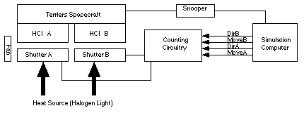
Figure 10: Horizon Crossing Indicator Stimulator
The shutters are constructed from cardboard because it is light enough for quick movement
under small torques, with good insulating properties for improved HCI trigger response,
and will not damage the spacecraft in the event of a shutter malfunction. By covering the cardboard shutters with tape, particulate generation can be reduced
enough to use them in the TERRIERS class-10,000 clean room. The shutters are connected
directly to the HCI's with a friction fitted keyed aluminum mounting plate that prevents them from shifting during HITL runs or changing position between runs.
Shutter timing commands are generated by an autonomous process running continuously
and in parallel with the simulation of the vehicle dynamics on the simulation computer.
Communication between the simulation and the timing loop is done by shared memory. This process has 1 msec resolution and roughly 24 hour maximum duration. This implementation
of the timing loop allows for accurate placement of the shutter commands over short
timescales. However, it does introduce a long-term drift in these same timing signals since it is not synchronized with the simulation computer.
Figure 11 shows the performance of the horizon crossing indicator stimulators in the
HITL test. Stimulation of the HCI's yield roll angle errors of 1.25 deg to 0.5 deg
over a 5 deg range. At zero roll angle, there is approximately zero roll error.
The error in spin rate is generally zero mean with a standard deviation of about 0.5
deg/sec. Several outlying data points, however, increase this error to as much at
20 deg/sec in some cases. It is believed that these outlying points are the results
of errors in the data collection process and not due to problems with the stimulators, simulation
process or the TERRIERS ACS.
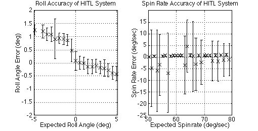
Figure 11: Performance of HCI Stimulators
Hardware-in-the-Loop Test Results
Several tests have been conducted using the hardware-in-the-loop test setup. These
include a number of short runs simulating various stages of the tip-off to sun-pointing
phase of the mission, one six-hour test running from tip-off to sun-pointing and
one four-hour operational test. The results of the six-hour test starting at launch
vehicle tip-off are presented in Figure 12. Initialized in a tumble with an arbitrary
initial attitude, the vehicle moves through its mode switching logic from Wait Mode,
briefly into Detumble Mode and then into Spin-Up Mode. The ACS spins up the vehicle
to about 4 deg/sec and then switches into sun-pointing mode. In this mode it continues
to spin the vehicle up to 6 deg/sec and then regulates the spin rate. While this
HITL test was being conducted, other spacecraft tests were performed. These included
regular radio contacts and a test of the power shedding logic. At the start of the
simulation, the spacecraft was disconnected from its power-supply and run completely
off batteries. At approximately 70 minutes into the simulation, the power shedding logic
detected a decrease in battery capacity and switched the ACS into Ground Command
Mode to conserve power. After validating this code, the power supply was reconnected
and the ACS was switched back into its Sun-Acquisition Mode and allowed to continue
its operations. However, the spacecraft software was not properly configured and
the sun vectors computed by the spacecraft were in error, thus invalidating the sun-acquisition portion of the test.
Fortunately, tests conducted previously indicate that the Sun-Acquisition Mode operates
properly (Figure 13). In this case the spacecraft is initialized with a spin-rate
of 6 deg/sec and an attitude where the solar panel is pointed away from the sun.
The ACS regulates the spin rate and begins to move the vehicle into a sun-pointing configuration,
shown by the increase in the component of the sun vector along the body y-axis.
One test of TERRIERS in its Operational Mode was conducted (Figure 14). The simulation
computer was initialized with a roll error of 2 deg and an initial spin rate of 60
deg/sec (10 RPM). After four hours, the operational controller had reduced the roll error to less than 1 deg. The yaw angle, because it is coupled to the roll angle,
was also reduced to less than 1 deg. The spin rate shows a slow increase from 60
deg/sec to 60.4 deg/sec, but this is within the error in the ability of the HCI stimulators to generate spin rates. Certainly, longer HITL tests will be conducted to verify
the stability of the spin rate controller. The spin rates in the x and z axes are
kept below 0.01 deg/sec, indicating that the polhode motion of the spin axis was
also controlled.
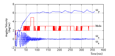
Figure 12: HITL Spin-Up Test Results
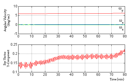
Figure 13: HITL Sun-Acquisition Results
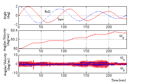
Figure 14: HITL Operational Mode Results
Conclusions
Low-cost spacecraft require a balance between what would be desirable for ACS testing
and what can be achieved under budgetary constraints. The goal is to achieve a large
fraction of the confidence that a more complete HITL test would provide for a small fraction of the effort that such a test would require.
AeroAstro LLC has designed, manufactured and tested the attitude control system for
the TERRIERS satellite. In addition, a complete hardware-in-the-loop test setup
has been created and validated. Tests using the HITL setup demonstrate the stability
and effectiveness of the Operational Mode controllers and the Detumble and Spin-Up Mode
controllers. Preliminary results indicate that the Sun-Acquisition controller is
also operating properly. Future HITL tests will verify its stability. The HITL
setup will be used during mission simulation where the spacecraft and payload will be exercised
continuously for weeks at a time, thus building confidence in the total spacecraft
system as the TERRIERS program moves to its launch.
Acknowledgements
The authors would like to acknowledge the efforts of several people who have contributed
to the design, manufacturing and test of the TERRIERS attitude control system: Frank
LaRosa, Scott McDermott, Sarah Wright, Joe Kendall, Angie Cuccio, Eric Aamot and Rob Baltrum.
References
Bate, Roger R., Donald D. Mueller, Jerry E. White. Fundamentals of Astrodynamics
.. New York: Dover Publications, Inc., 1971.
Kane, Thomas R., Peter W. Likins, and David A. Levinson. Spacecraft Dynamics
. New York: McGraw-Hill, Inc., 1983.
Spacecraft Attitude Determination and Control
. James R. Wertz, ed. Netherlands: Kluwer Academic Publishers, 1978.


